BGP Routing Protocol Practice Lab 01


BGP Routing Protocol Practice Lab 01


Lab 1: MED and AS-Path Prepend


Basic configuration

R1:

interface Loopback0

ip address 1.1.1.1 255.255.255.255

!

interface FastEthernet0/0 
ip address 150.1.1.1 255.255.255.0
 no shut

!

interface Serial0/0

ip address 10.0.0.1 255.255.255.252

no shut

R2:

interface Loopback0

ip address 2.2.2.2 255.255.255.255

!

interface Loopback192

ip address 192.1.1.1 255.255.255.0

!

interface Loopback193

ip address 193.1.1.1 255.255.255.0

!

interface Loopback194

ip address 194.1.1.1 255.255.255.0

!

interface Loopback195

ip address 195.1.1.1 255.255.255.0

!

interface Serial0/0

ip address 10.0.0.2 255.255.255.252

no shut !

interface Serial0/1

ip address 10.0.0.9 255.255.255.252

no shut


R3:

interface Loopback0

ip address 3.3.3.3 255.255.255.255

!

interface FastEthernet0/0 ip address 150.3.3.3 255.255.255.0 no shut

!

interface Serial0/1

ip address 10.0.0.10 255.255.255.252

no shut !

interface Serial0/2

ip address 10.0.0.13 255.255.255.252

no shut !

interface Serial0/3

ip address 10.0.0.17 255.255.255.252

no shut


R4:


interface Loopback0

ip address 4.4.4.4 255.255.255.255

!

interface FastEthernet0/0 ip address 150.1.1.4 255.255.255.0 no shut

!

interface Serial0/0

ip address 10.0.0.14 255.255.255.252

no shut !

interface Serial0/1

ip address 10.0.0.18 255.255.255.252

no shut


Configure BGP as illustrated in the topology. Use the Loopback 0 addresses for peering. Do NOT configure any IGPs. Instead, use static routes only. R1 should peer with R2 and R4. R2 should peer with R1 and R3. R3 should peer with R2 and R4. R4 should peer with R1 and R3.


R1(config)#ip route 2.2.2.2 255.255.255.255 serial 0/0

R1(config)#ip route 4.4.4.4 255.255.255.255 fastethernet 0/0 150.1.1.4

R1(config)#router bgp 1

R1(config-router)#neighbor 2.2.2.2 remote-as 2

R1(config-router)#neighbor 2.2.2.2 update-source loopback 0

R1(config-router)#neighbor 2.2.2.2 ebgp-multihop 3

R1(config-router)#neighbor 4.4.4.4 remote-as 4

R1(config-router)#neighbor 4.4.4.4 update-source loopback 0

R1(config-router)#neighbor 4.4.4.4 ebgp-multihop 3


R2(config)#ip route 1.1.1.1 255.255.255.255 serial 0/0

R2(config)#ip route 3.3.3.3 255.255.255.255 serial 0/1

R2(config)#router bgp 2

R2(config-router)#neighbor 1.1.1.1 remote-as 1

R2(config-router)#neighbor 1.1.1.1 update-source loopback 0

R2(config-router)#neighbor 1.1.1.1 ebgp-multihop 3

R2(config-router)#neighbor 3.3.3.3 remote-as 3

R2(config-router)#neighbor 3.3.3.3 update-source loopback 0

R2(config-router)#neighbor 3.3.3.3 ebgp-multihop 3


R3(config)#ip route 2.2.2.2 255.255.255.255 serial 1/1

R3(config)#ip route 4.4.4.4 255.255.255.255 serial 1/2

R3(config)#ip route 4.4.4.4 255.255.255.255 serial 1/3

R3(config)#router bgp 3

R3(config-router)#neighbor 2.2.2.2 remote-as 2

R3(config-router)#neighbor 2.2.2.2 update-source loopback 0

R3(config-router)#neighbor 2.2.2.2 ebgp-multihop 3

R3(config-router)#neighbor 4.4.4.4 remote-as 4

R3(config-router)#neighbor 4.4.4.4 update-source loopback 0

R3(config-router)#neighbor 4.4.4.4 ebgp-multihop 3


R4(config)#ip route 1.1.1.1 255.255.255.255 fastethernet 0/0 150.1.1.1

R4(config)#ip route 3.3.3.3 255.255.255.255 serial 0/0

R4(config)#ip route 3.3.3.3 255.255.255.255 serial 0/1

R4(config)#router bgp 4

R4(config-router)#neighbor 1.1.1.1 remote-as 1

R4(config-router)#neighbor 1.1.1.1 update-source loopback 0

R4(config-router)#neighbor 1.1.1.1 ebgp-multihop 3

R4(config-router)#neighbor 3.3.3.3 remote-as 3

R4(config-router)#neighbor 3.3.3.3 update-source loopback 0

R4(config-router)#neighbor 3.3.3.3 ebgp-multihop 3


In order to ensure that the ORIGIN code is INCOMPLETE, you need to redistribute the LAN subnets into BGP. However, you can also use the network statement in conjunction with a route map and set the ORIGIN code within the route map.


R1(config)#route-map CONNECTED permit 10

R1(config-route-map)#match interface fastethernet 0/0

R1(config-route-map)#exit

R1(config)#route-map CONNECTED deny 20

R1(config-route-map)#exit

R1(config)#router bgp 1

R1(config-router)#redistribute connected route-map CONNECTED R1(config-router)#exit


You can verify the ORIGIN code by looking at the prefix entry in the BGP Tables. The ORIGIN code of INCOMPLETE is denoted by a question mark (?) in the output of the show ip bgp command. You can view additional detail on a per-prefix basis also when using this command


show ip bgp


show ip bgp


show ip bgp

show ip bgp


Configure BGP, so that R4 prefers the path via R3 to reach any subnet

In the output of the show ip bgp command on R4 we can see that the preferred route to reach 150.3.3.0 is via R3, however the preferred route to reach 150.2.2.0 is via R1 (the lowest routerid), also, to ensure that the subnet 150.1.1.0 will be reached via R3, configure BGP on R1 to advertise all prefixes with a longer AS-PATH to influence the path selection as follow:


R1(config)#route-map PREP permit 10

R1(config-route-map)#set as-path prepend 1 1 1 1 R1(config-route-map)#exit

R1(config)#router bgp 1

R1(config-router)#neighbor 4.4.4.4 route-map PREP out R1(config-router)#exit


Notice now the preferred path to reach both prefixes 150.3.3.0 and 150.2.2.0 is via R3 with the next-hop 3.3.3.3 because the shortest AS-PATH length:


do show ip bgp


Configure R4 so that it sends all updates to R3 with a MED of 4. Configure R2 so that it sends all updates to R3 with a MED of 2. Ensure that R3 prefers all routes with the better (lower) MED value.

Before configuring the MED let's verify the BGP RIBs on R3:

The preferred path to reach the prefix 150.1.1.0 is via R4, we should see all routes with the next-hop R2:


Let's configure MED


Let's configure MED on R3:

R4(config)#route-map MED permit 10

R4(config-route-map)#set metric 4

R4(config-route-map)#exit

R4(config)#router bgp 4

R4(config-router)#neighbor 3.3.3.3 route-map MED out

R4(config-router)#exit


R2(config)#route-map MED permit 10

R2(config-route-map)#set metric 2

R2(config-route-map)#exit

R2(config)#router bgp 2


R2(config-router)#neighbor 3.3.3.3 route-map MED out

R2(config-router)#exit


Let's verify the BGP RIBs of R3:

We have still the best path to reach 150.1.1.0 via R4 as shown by the show ip bgp command on R3 below, so the problem is not resolved even if R2 advertises the lowest MED comparing with R4.

The reason is: we met two issues in this case:

-the first issue is: by default, the MED is only compared for path received from the same AS ,in this case R3 receives two values of MED from two routers (R2 and R4) configured in different AS.

-The second issue: the MED is compared after the AS-PATH in the BGP decision process. In this case R3 will select the path via R4 as the best path to the 150.1.1.0/24 prefix because of the shorter AS-PATH length.


BGP MED


To override the two issues, configure the bgp always-compare-med command to avoid the first issue so always compare the MED even if MED is received from Different AS. And bgp bestpath as-path ignore command to avoid the second issue so that R3 override the BGP decision process by ignoring the step of the AS-PATH in the BGP Decision Process:

Let's configure these two commands:


R3(config)#router bgp 3

R3(config-router)#bgp bestpath as-path ignore R3(config-router)#bgp always-compare-med


We can see for the prefix 150.1.1.0 that the path with the longer AS-PATH length is preferred because the lowest MED even if the AS-PATH takes precedence over the MED in the order of the path selection in BGP:


BGP


Another way to verify all BGP RIBs with do show ip bgp, R3 prefers all routes from R2 because the lowest MED:


#BGP #LAB #CCNA #CCNP #CCIE #cisco #gns3 #solution


OSPF Multi-Area Configuration


OSPF Multi-Area Configurationg


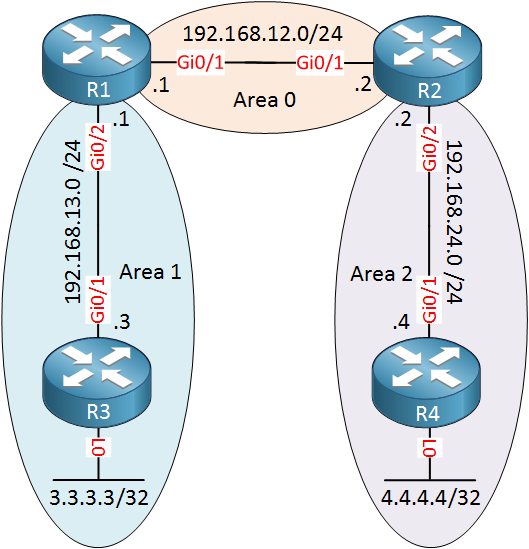
We will use the following topology:

ospf two areas multi area

Above we have R1 and R2 in area 0, the backbone area. Between R1 and R3, we will use area 1 and between R2/R4 we will use area 2. R3 and R4 have a loopback interface with an IP address that we will advertise in their area.

Configuration


Let’s start with all network commands to get OSPF up and running. The network command defines to which area each interface will belong.First, we will configure R1 and R2 for the backbone area:

R1(config)#router ospf 1
R1(config-router)#network 192.168.12.0 0.0.0.255 area 0
R2(config)#router ospf 1
R2(config-router)#network 192.168.12.0 0.0.0.255 area 0

Let’s configure R1 and R3 for area 1:

R1(config)#router ospf 1
R1(config-router)#network 192.168.13.0 0.0.0.255 area 1
R3(config)#router ospf 1
R3(config-router)#network 192.168.13.0 0.0.0.255 area 1
R3(config-router)#network 3.3.3.3 0.0.0.0 area 1

And last but not least, R2 and R4 for area 2:

R2(config)#router ospf 1
R2(config-router)#network 192.168.24.0 0.0.0.255 area 2
R4(config)#router ospf 1
R4(config-router)#network 192.168.24.0 0.0.0.255 area 2
R4(config-router)#network 4.4.4.4 0.0.0.0 area 2

Those are all the network commands we need.

Verification

Let’s verify our work. First, let’s make sure we have OSPF neighbors:

R1#show ip ospf neighbor 

Neighbor ID     Pri   State           Dead Time   Address         Interface
192.168.24.2      1   FULL/DR         00:00:36    192.168.12.2    GigabitEthernet0/1
3.3.3.3           1   FULL/BDR        00:00:34    192.168.13.3    GigabitEthernet0/2

R1 has formed a neighbor adjacency with R2 and R3. Let’s check R2:

R2#show ip ospf neighbor

Neighbor ID     Pri   State           Dead Time   Address         Interface
192.168.13.1      1   FULL/BDR        00:00:34    192.168.12.1    GigabitEthernet0/1
4.4.4.4           1   FULL/BDR        00:00:30    192.168.24.4    GigabitEthernet0/2

R2 has formed neighbor adjacencies with R1 and R4. The show ip ospf neighbor command, however, doesn’t tell me anything about the areas that are used. If you want to see this, you could add the detail parameter like this:

R2#show ip ospf neighbor detail 
 Neighbor 192.168.13.1, interface address 192.168.12.1
    In the area 0 via interface GigabitEthernet0/1
    Neighbor priority is 1, State is FULL, 6 state changes
    DR is 192.168.12.2 BDR is 192.168.12.1
    Options is 0x12 in Hello (E-bit, L-bit)
    Options is 0x52 in DBD (E-bit, L-bit, O-bit)
    LLS Options is 0x1 (LR)
    Dead timer due in 00:00:33
    Neighbor is up for 00:17:30
    Index 1/1/1, retransmission queue length 0, number of retransmission 0
    First 0x0(0)/0x0(0)/0x0(0) Next 0x0(0)/0x0(0)/0x0(0)
    Last retransmission scan length is 0, maximum is 0
    Last retransmission scan time is 0 msec, maximum is 0 msec
 Neighbor 4.4.4.4, interface address 192.168.24.4
    In the area 2 via interface GigabitEthernet0/2
    Neighbor priority is 1, State is FULL, 6 state changes
    DR is 192.168.24.2 BDR is 192.168.24.4
    Options is 0x12 in Hello (E-bit, L-bit)
    Options is 0x52 in DBD (E-bit, L-bit, O-bit)
    LLS Options is 0x1 (LR)
    Dead timer due in 00:00:31
    Neighbor is up for 00:15:57
    Index 1/1/2, retransmission queue length 0, number of retransmission 0
    First 0x0(0)/0x0(0)/0x0(0) Next 0x0(0)/0x0(0)/0x0(0)
    Last retransmission scan length is 0, maximum is 0
    Last retransmission scan time is 0 msec, maximum is 0 msec

Above you can see that interface GigabitEthernet0/1 is in area 0 and interface GigabitEthernet0/2 is in area 2. Another good command to find area information is show ip protocols:

R2#show ip protocols 
*** IP Routing is NSF aware ***

Routing Protocol is "application"
  Sending updates every 0 seconds
  Invalid after 0 seconds, hold down 0, flushed after 0
  Outgoing update filter list for all interfaces is not set
  Incoming update filter list for all interfaces is not set
  Maximum path: 32
  Routing for Networks:
  Routing Information Sources:
    Gateway         Distance      Last Update
  Distance: (default is 4)

Routing Protocol is "ospf 1"
  Outgoing update filter list for all interfaces is not set
  Incoming update filter list for all interfaces is not set
  Router ID 192.168.24.2
  It is an area border router
  Number of areas in this router is 2. 2 normal 0 stub 0 nssa
  Maximum path: 4
  Routing for Networks:
    192.168.12.0 0.0.0.255 area 0
    192.168.24.0 0.0.0.255 area 2
  Routing Information Sources:
    Gateway         Distance      Last Update
    4.4.4.4              110      00:16:04
    192.168.13.1         110      00:16:53
  Distance: (default is 110)

Above you can see which networks belong to which area:

  • Network 192.168.12.0 in area 0.
  • Network 192.168.24.0 in area 2.

Let’s check our routing tables. Let’s start with R1:

R1#show ip route ospf
Codes: L - local, C - connected, S - static, R - RIP, M - mobile, B - BGP
       D - EIGRP, EX - EIGRP external, O - OSPF, IA - OSPF inter area 
       N1 - OSPF NSSA external type 1, N2 - OSPF NSSA external type 2
       E1 - OSPF external type 1, E2 - OSPF external type 2
       i - IS-IS, su - IS-IS summary, L1 - IS-IS level-1, L2 - IS-IS level-2
       ia - IS-IS inter area, * - candidate default, U - per-user static route
       o - ODR, P - periodic downloaded static route, H - NHRP, l - LISP
       a - application route
       + - replicated route, % - next hop override, p - overrides from PfR

Gateway of last resort is not set

      3.0.0.0/32 is subnetted, 1 subnets
O        3.3.3.3 [110/2] via 192.168.13.3, 00:01:47, GigabitEthernet0/2
      4.0.0.0/32 is subnetted, 1 subnets
O IA     4.4.4.4 [110/3] via 192.168.12.2, 00:00:54, GigabitEthernet0/1
O IA  192.168.24.0/24 [110/2] via 192.168.12.2, 00:01:44, GigabitEthernet0/1

Above we see three OSPF entries. The first one is for 3.3.3.3/32, the loopback interface of R3. It shows up with an O since this is an intra-area route. R1 has also learned about 4.4.4.4/32 and 192.168.24.0/24. These two entries show up as O IA since they are inter-area routes.

R2 has a similar output:

R2#show ip route ospf

      3.0.0.0/32 is subnetted, 1 subnets
O IA     3.3.3.3 [110/3] via 192.168.12.1, 00:02:19, GigabitEthernet0/1
      4.0.0.0/32 is subnetted, 1 subnets
O        4.4.4.4 [110/2] via 192.168.24.4, 00:01:29, GigabitEthernet0/2
O IA  192.168.13.0/24 [110/2] via 192.168.12.1, 00:02:24, GigabitEthernet0/1

Above we see that R2 has learned about 3.3.3.3/32 and 192.168.13.0/24 which area inter-area routes. 4.4.4.4/32 is an intra-area route.

Let’s check R3:

R3#show ip route ospf

      4.0.0.0/32 is subnetted, 1 subnets
O IA     4.4.4.4 [110/4] via 192.168.13.1, 00:01:57, GigabitEthernet0/1
O IA  192.168.12.0/24 [110/2] via 192.168.13.1, 00:02:50, GigabitEthernet0/1
O IA  192.168.24.0/24 [110/3] via 192.168.13.1, 00:02:47, GigabitEthernet0/1

Everything that R3 has learned is from another area, that’s why we only see inter-area routes here. The same thing applies to R4:

R4#show ip route ospf

      3.0.0.0/32 is subnetted, 1 subnets
O IA     3.3.3.3 [110/4] via 192.168.24.2, 00:02:13, GigabitEthernet0/1
O IA  192.168.12.0/24 [110/2] via 192.168.24.2, 00:02:13, GigabitEthernet0/1
O IA  192.168.13.0/24 [110/3] via 192.168.24.2, 00:02:13, GigabitEthernet0/1

Just to be sure, let’s try a quick ping between R3 and R4 to prove that our multi-area OSPF configuration is working:

R3#ping 4.4.4.4 source 3.3.3.3
Type escape sequence to abort.
Sending 5, 100-byte ICMP Echos to 4.4.4.4, timeout is 2 seconds:
Packet sent with a source address of 3.3.3.3 
!!!!!
Success rate is 100 percent (5/5), round-trip min/avg/max = 9/11/13 ms

Our ping is successful. That will be all for now.

Hot Standby Router Protocol (HSRP)


Hot Standby Router Protocol (HSRP)


#cybersecurity #coursera #quiz #solution #network
HSRP 2 different networks configurations and verification


Hot Standby Router Protocol (HSRP) is a CISCO proprietary protocol, which provides redundancy for a local subnet. In HSRP, two or more routers gives an illusion of a virtual router.

HSRP allows you to configure two or more routers as standby routers and only a single router as an active router at a time. All the routers in a single HSRP group shares a single MAC address and IP address, which acts as a default gateway to the local network. The Active router is responsible for forwarding the traffic. If it fails, the Standby router takes up all the responsibilities of the active router and forwards the traffic.

Some important terms related to HSRP :

  1. Virtual IP : IP address from local subnet is assigned as default gateway to all local hosts in the network.
  2. Virtual MAC address : MAC address is generated automatically by HSRP. The first 24 bits will be default CISCO address (i.e. 0000.0c). The next 16 bits are HSRP ID (i.e. 07.ac). The next 8 bits will be the group number in hexadecimal. e.g- if the group number is 10 then the last 8 bits will be 0a.
     
    Example of virtual MAC address –
    0000.0c07.ac0a
  3. Hello messages : Periodic messages exchanged by active and standby routers. These messages are exchanged after every 3 seconds telling the state of router.
  4. Hold down timer : Its default value is 10 seconds i.e roughly 3 times the value of hello message. This timer tells us about the router that how much time will the standby router waits for hello message if it is not received on time.

    Note : If the active router fails then the standby router will become the active router.

  5. Priority : By default, the priority value is 100. It is helpful when the active router comes back after falling down, we can change the priority of standby router (which has become the active router after the original active router is down) to less than 100 therefore it again becomes standby router.

    Note : The router having higher priority will become the active router.

  6. Preempt : It is a state in which the standby router automatically becomes the active router.

WORKING :

Members having same group ID are the members of same group. One of the member of the group will be elected as the active router while others remain as standby routers. The virtual IP is configured as default gateway of all the hosts in the local subnet and the active router is responsible for forwarding the traffic of local hosts. If the active router goes down then the hello messages are not exchanged between the active and the standby routers therefore the standby router waits until the hold-down timer time. As soon as the hold down time is finished, the standby router will become the active router and take up all the responsibilities of active router. This is known as preempt.
If in case the original active router comes back then we can decrease the priority of the standby router so that it will become the standby router again.

Hot Standby Router Protocol (HSRP) has 2-versions :

version 1 : The messages are multicast at 224.0.0.2 and uses the UDP port 1985. This version allows group number range from 0 to 255.
version 2 : The messages are multicast at 224.0.0.102 and uses the UDP port 1985. This version allows group number range from 0 to 4095.

DR and BDR selection Lab

 #ospf #protocol #configuration #lab #DR #BDR


Lab objectives:

Ensure router R1 is the DR for network 100.1.1.0 /24.

Ensure router R3 is the BDR for network 100.1.1.0 /24.

Ensure router R5 is the DR for network 100.1.2.0 /24. without changing the priority

Ensure router R2 is the BDR for network 100.1.2.0 /24. You are not allowed to change the priority.


Solution configurations:

R1:

conf t

int fa 0/0

ip address 100.1.1.2 255.255.255.0

no shutdown

exit

router ospf 10

network 100.1.1.0 0.0.0.255 area 0

network 100.1.2.0 0.0.0.255 area 0

log-adjacency-changes

conf t

router ospf 10

log-adjacency-changes

exit

exit


R2:


the solution to achieve all objectives:

change priority of R1 must be higher than R3

change priority of R2 must be lower than R1

change router-id manually to higher router ID 120.120.120.2 


Featured Post

Day 41 — BGP Confederations: Sub-AS Design, External View and Migration

1. Opening Confederations are another way to scale BGP inside a large administrative domain. They divide the domain into member autonomous systems while presenting a single confederation identifier to external peers. They are powerful, but their operational model is more complex than simply 'using private ASNs inside.' The engineering goal is not to memorize another BGP command. It is to understand what information each speaker is allowed to propagate, what path information can be hidden, and what failure domain is created by the chosen control-plane architecture . 2. Concept and standards behavior RFC 5065 defines AS_CONFED_SEQUENCE and AS_CONFED_SET and how member-AS relationships are represented. Confederation external sessions have eBGP-like properties inside the confederation, while the confederation is presented externally as one AS. Modern guidance must also account for the fact that RFC 9774 prohibits new origination of AS_SET/AS_CONFED_SET in ordinary aggregation c...