Why do we need i-BGP for the routes when we have the IGP protocols (OSPF, IS-IS) for internal communication within the AS?

 Why do we need i-BGP for the routes when we have the IGP protocols (OSPF, IS-IS) for internal communication within the AS?


IGPs like OSPF or ISIS, are link-state protocols that give us all the information of the network and allow for very interesting convergence options and traffic engineering options. Whereas, BGP knows a very limited view of the network as a whole because BGP handles very well filtering and modifying routing information.


See, the traffic in a network can be divided into 4 categories.

• Ingress: traffic arriving from outside the network, destined for hosts within the network.

• Egress: traffic originating inside the network destined for hosts outside the network.

• Internal: traffic where both the origin and destination are within the network.

• Transit: traffic where both the origin and destination are outside the network.


The IGP normally carries internal routes, so it can be used to directly route ingress and internal traffic, but what about egress and transit traffic?


There are three choices -

• Use iBGP

• Use default routes.

• Redistribute external routes into your iGP.


Redistributing the whole internet routing table into your iGP will not end well. iGPs simply are not designed to deal with hundreds of thousands of routes.


If you have only one router that connects to the outside world, then you don't need iBGP. You can simply use a default route to direct egress traffic to your border router. If you have multiple routers that connect to providers then you can still use default routes, but by doing so you lose some of the advantages of multi-homing.


So, we'll be using i-BGP because of Scalability.

Thus, iBGP is required unless you're willing to redistribute all the routes.


#ibgp #bgp #network #cisco #huawei #free #learning

OSPF Multi-Area Configuration


OSPF Multi-Area Configurationg


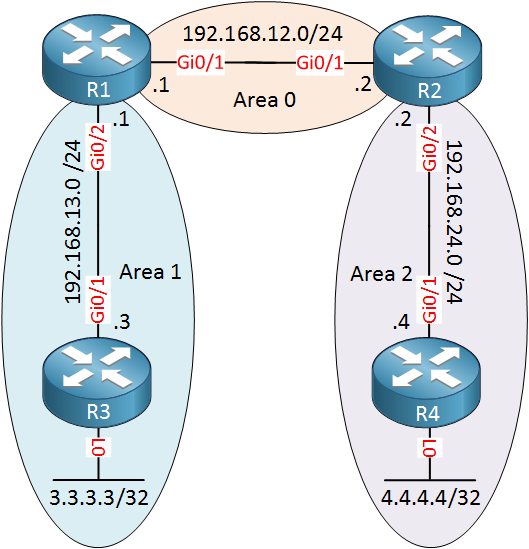
We will use the following topology:

ospf two areas multi area

Above we have R1 and R2 in area 0, the backbone area. Between R1 and R3, we will use area 1 and between R2/R4 we will use area 2. R3 and R4 have a loopback interface with an IP address that we will advertise in their area.

Configuration


Let’s start with all network commands to get OSPF up and running. The network command defines to which area each interface will belong.First, we will configure R1 and R2 for the backbone area:

R1(config)#router ospf 1
R1(config-router)#network 192.168.12.0 0.0.0.255 area 0
R2(config)#router ospf 1
R2(config-router)#network 192.168.12.0 0.0.0.255 area 0

Let’s configure R1 and R3 for area 1:

R1(config)#router ospf 1
R1(config-router)#network 192.168.13.0 0.0.0.255 area 1
R3(config)#router ospf 1
R3(config-router)#network 192.168.13.0 0.0.0.255 area 1
R3(config-router)#network 3.3.3.3 0.0.0.0 area 1

And last but not least, R2 and R4 for area 2:

R2(config)#router ospf 1
R2(config-router)#network 192.168.24.0 0.0.0.255 area 2
R4(config)#router ospf 1
R4(config-router)#network 192.168.24.0 0.0.0.255 area 2
R4(config-router)#network 4.4.4.4 0.0.0.0 area 2

Those are all the network commands we need.

Verification

Let’s verify our work. First, let’s make sure we have OSPF neighbors:

R1#show ip ospf neighbor 

Neighbor ID     Pri   State           Dead Time   Address         Interface
192.168.24.2      1   FULL/DR         00:00:36    192.168.12.2    GigabitEthernet0/1
3.3.3.3           1   FULL/BDR        00:00:34    192.168.13.3    GigabitEthernet0/2

R1 has formed a neighbor adjacency with R2 and R3. Let’s check R2:

R2#show ip ospf neighbor

Neighbor ID     Pri   State           Dead Time   Address         Interface
192.168.13.1      1   FULL/BDR        00:00:34    192.168.12.1    GigabitEthernet0/1
4.4.4.4           1   FULL/BDR        00:00:30    192.168.24.4    GigabitEthernet0/2

R2 has formed neighbor adjacencies with R1 and R4. The show ip ospf neighbor command, however, doesn’t tell me anything about the areas that are used. If you want to see this, you could add the detail parameter like this:

R2#show ip ospf neighbor detail 
 Neighbor 192.168.13.1, interface address 192.168.12.1
    In the area 0 via interface GigabitEthernet0/1
    Neighbor priority is 1, State is FULL, 6 state changes
    DR is 192.168.12.2 BDR is 192.168.12.1
    Options is 0x12 in Hello (E-bit, L-bit)
    Options is 0x52 in DBD (E-bit, L-bit, O-bit)
    LLS Options is 0x1 (LR)
    Dead timer due in 00:00:33
    Neighbor is up for 00:17:30
    Index 1/1/1, retransmission queue length 0, number of retransmission 0
    First 0x0(0)/0x0(0)/0x0(0) Next 0x0(0)/0x0(0)/0x0(0)
    Last retransmission scan length is 0, maximum is 0
    Last retransmission scan time is 0 msec, maximum is 0 msec
 Neighbor 4.4.4.4, interface address 192.168.24.4
    In the area 2 via interface GigabitEthernet0/2
    Neighbor priority is 1, State is FULL, 6 state changes
    DR is 192.168.24.2 BDR is 192.168.24.4
    Options is 0x12 in Hello (E-bit, L-bit)
    Options is 0x52 in DBD (E-bit, L-bit, O-bit)
    LLS Options is 0x1 (LR)
    Dead timer due in 00:00:31
    Neighbor is up for 00:15:57
    Index 1/1/2, retransmission queue length 0, number of retransmission 0
    First 0x0(0)/0x0(0)/0x0(0) Next 0x0(0)/0x0(0)/0x0(0)
    Last retransmission scan length is 0, maximum is 0
    Last retransmission scan time is 0 msec, maximum is 0 msec

Above you can see that interface GigabitEthernet0/1 is in area 0 and interface GigabitEthernet0/2 is in area 2. Another good command to find area information is show ip protocols:

R2#show ip protocols 
*** IP Routing is NSF aware ***

Routing Protocol is "application"
  Sending updates every 0 seconds
  Invalid after 0 seconds, hold down 0, flushed after 0
  Outgoing update filter list for all interfaces is not set
  Incoming update filter list for all interfaces is not set
  Maximum path: 32
  Routing for Networks:
  Routing Information Sources:
    Gateway         Distance      Last Update
  Distance: (default is 4)

Routing Protocol is "ospf 1"
  Outgoing update filter list for all interfaces is not set
  Incoming update filter list for all interfaces is not set
  Router ID 192.168.24.2
  It is an area border router
  Number of areas in this router is 2. 2 normal 0 stub 0 nssa
  Maximum path: 4
  Routing for Networks:
    192.168.12.0 0.0.0.255 area 0
    192.168.24.0 0.0.0.255 area 2
  Routing Information Sources:
    Gateway         Distance      Last Update
    4.4.4.4              110      00:16:04
    192.168.13.1         110      00:16:53
  Distance: (default is 110)

Above you can see which networks belong to which area:

  • Network 192.168.12.0 in area 0.
  • Network 192.168.24.0 in area 2.

Let’s check our routing tables. Let’s start with R1:

R1#show ip route ospf
Codes: L - local, C - connected, S - static, R - RIP, M - mobile, B - BGP
       D - EIGRP, EX - EIGRP external, O - OSPF, IA - OSPF inter area 
       N1 - OSPF NSSA external type 1, N2 - OSPF NSSA external type 2
       E1 - OSPF external type 1, E2 - OSPF external type 2
       i - IS-IS, su - IS-IS summary, L1 - IS-IS level-1, L2 - IS-IS level-2
       ia - IS-IS inter area, * - candidate default, U - per-user static route
       o - ODR, P - periodic downloaded static route, H - NHRP, l - LISP
       a - application route
       + - replicated route, % - next hop override, p - overrides from PfR

Gateway of last resort is not set

      3.0.0.0/32 is subnetted, 1 subnets
O        3.3.3.3 [110/2] via 192.168.13.3, 00:01:47, GigabitEthernet0/2
      4.0.0.0/32 is subnetted, 1 subnets
O IA     4.4.4.4 [110/3] via 192.168.12.2, 00:00:54, GigabitEthernet0/1
O IA  192.168.24.0/24 [110/2] via 192.168.12.2, 00:01:44, GigabitEthernet0/1

Above we see three OSPF entries. The first one is for 3.3.3.3/32, the loopback interface of R3. It shows up with an O since this is an intra-area route. R1 has also learned about 4.4.4.4/32 and 192.168.24.0/24. These two entries show up as O IA since they are inter-area routes.

R2 has a similar output:

R2#show ip route ospf

      3.0.0.0/32 is subnetted, 1 subnets
O IA     3.3.3.3 [110/3] via 192.168.12.1, 00:02:19, GigabitEthernet0/1
      4.0.0.0/32 is subnetted, 1 subnets
O        4.4.4.4 [110/2] via 192.168.24.4, 00:01:29, GigabitEthernet0/2
O IA  192.168.13.0/24 [110/2] via 192.168.12.1, 00:02:24, GigabitEthernet0/1

Above we see that R2 has learned about 3.3.3.3/32 and 192.168.13.0/24 which area inter-area routes. 4.4.4.4/32 is an intra-area route.

Let’s check R3:

R3#show ip route ospf

      4.0.0.0/32 is subnetted, 1 subnets
O IA     4.4.4.4 [110/4] via 192.168.13.1, 00:01:57, GigabitEthernet0/1
O IA  192.168.12.0/24 [110/2] via 192.168.13.1, 00:02:50, GigabitEthernet0/1
O IA  192.168.24.0/24 [110/3] via 192.168.13.1, 00:02:47, GigabitEthernet0/1

Everything that R3 has learned is from another area, that’s why we only see inter-area routes here. The same thing applies to R4:

R4#show ip route ospf

      3.0.0.0/32 is subnetted, 1 subnets
O IA     3.3.3.3 [110/4] via 192.168.24.2, 00:02:13, GigabitEthernet0/1
O IA  192.168.12.0/24 [110/2] via 192.168.24.2, 00:02:13, GigabitEthernet0/1
O IA  192.168.13.0/24 [110/3] via 192.168.24.2, 00:02:13, GigabitEthernet0/1

Just to be sure, let’s try a quick ping between R3 and R4 to prove that our multi-area OSPF configuration is working:

R3#ping 4.4.4.4 source 3.3.3.3
Type escape sequence to abort.
Sending 5, 100-byte ICMP Echos to 4.4.4.4, timeout is 2 seconds:
Packet sent with a source address of 3.3.3.3 
!!!!!
Success rate is 100 percent (5/5), round-trip min/avg/max = 9/11/13 ms

Our ping is successful. That will be all for now.

Protocol Redistribution EIGRP and OSPF route


 Find below the configurations for route redistribution between OSPF and EIGRP LAB.


R1 configurations:

configure terminal interface serial 1/1 ip address 4.1.1.2 255.0.0.0 no shut interface serial 1/0 ip address 1.1.1.1 255.0.0.0 no shut interface fastethernet 0/0 ip address 200.100.50.100 255.255.255.0 no shut router ospf 11 network 1.0.0.0 0.255.255.255 area 0 network 4.0.0.0 0.255.255.255 area 0 network 200.100.50.0 0.0.0.255 area 0 network 200.100.200.0 0.0.0.255 area 0 redistribute eigrp 10 subnets exit router eigrp 10 redistribute ospf 11 metric 1 1 1 1 1


R2 configurations:

configure terminal interface serial 1/0 ip address 1.1.1.2 255.0.0.0 no shut interface serial 1/1 ip address 2.1.1.1 255.0.0.0 no shut interface fastethernet 0/0 ip address 200.100.100.100 255.255.255.0 no shut router ospf 11 network 1.0.0.0 0.255.255.255 area 0 network 4.0.0.0 0.255.255.255 area 0 network 200.100.50.0 0.0.0.255 area 0 network 200.100.200.0 0.0.0.255 area 0 redistribute eigrp 10 subnets exit router eigrp 10 network 200.100.100.100 0.0.0.255 network 2.0.0.0 0.255.255.255 network 3.0.0.0 0.255.255.255 network 200.100.150.100 0.0.0.255 redistribute ospf 11 metric 1 1 1 1 1


R3 configurations:

configure terminal interface serial 1/1 ip address 2.1.1.2 255.0.0.0 no shut interface serial 1/0 ip address 3.1.1.1 255.0.0.0 no shut interface fastethernet 0/0 ip address 200.100.150.100 255.255.255.0 no keep alive no shut router eigrp 10 network 200.100.100.100 0.0.0.255 network 2.0.0.0 0.255.255.255 network 3.0.0.0 0.255.255.255 network 200.100.150.100 0.0.0.255 redistribute ospf 11 metric 1 1 1 1 1


R4 configurations:

configure terminal interface serial 1/1 ip address 4.1.1.1 255.0.0.0 no shut interface serial 1/0 ip address 3.1.1.2 255.0.0.0 no shut interface fastethernet 0/0 ip address 200.100.200.150 255.255.255.0 no shut router ospf 11 network 1.0.0.0 0.255.255.255 area 0 network 4.0.0.0 0.255.255.255 area 0 network 200.100.50.0 0.0.0.255 area 0 network 200.100.200.0 0.0.0.255 area 0 redistribute eigrp 10 subnets exit router eigrp 10 network 200.100.100.100 0.0.0.255 network 2.0.0.0 0.255.255.255 network 3.0.0.0 0.255.255.255 network 200.100.150.100 0.0.0.255 redistribute ospf 11 metric 1 1 1 1 1


EIGRP K-values


How to redistribute the different protocols route in each other. #OSPF #EIGRP #LAB #video #tutorial R4 s1/1 and f0/0 are in OSPF 11 area 0 R2 s1/0 in OSPF 11 area 0 s1/1 & F0/0 in EIGRP 10 R3 s1/1, s1/2, and f0/0 in EIGRP 10. for R3 if you see there is no device attached at fast ethernet interface. so how can we keep this interface active and make sure it doesn't need any hello packets? because we already know that there is no device connected but how to tell this to computer/Router/Network? we will later check this during configuration, meanwhile, you can share your answer in the comments. now let's go to configurations and first we will see the description of commands to check then we will start configurations. these are R1 configurations with their description. steps: 1. configure IP on interfaces and use no shutdown or no shut command to enable the interface. 2. create your OSPF process with your own process ID, I am using 11. 3. then advertise the networks in OSPF till line 16. so how do we choose the networks to advertise which belong to OSPF? for those who don't know check the topology and R1 all 3 interfaces R4 2 interfaces R2 1 interface is in OSPF 11 area 0, we have chosen by our self for each router the protocol we can change it as well. but for this lab, we have chosen as it is shown. so the first network if you see 1.0.0.0 is in b/w R1 and R2 on interfaces S1/0 on both sides. and then 4.0.0.0 b/w R1 and R4 on interfaces S1/1 on both sides in OSPF 11 area 0. and then there are 2 more networks on ethernet of R1 and R4 200.100.50.0/24, 200.100.200.0/24 similarly networks for EIGRP are advertised based on the actual connection R1 have 3 directly connected networks and 1 via OSPF we will verify this as well after configuration if we check from topology network 200.100.200.0/24 will be displayed in routing table as connected via OSPF. if you have any confusion do let me know in the comments box. ok, let's start the configurations. if you give the router command with? you can see the options of protocol configuration so here if you check for advertising network I have used the wild card mask instead of subnet mask wild card mask is opposite of the subnet mask. for detail reading and concept building you can search about it on google. here I have one question we have a wildcard mask while networking advertisement and as well in ACL access control list. so please share your answer in the comment box for difference between wildcard of ACL and OSPF?? share the answer in the comments it is showing only 1 route why?? . . . . . because we have not configured other connected interfaces. let's do and then we will come back and check. now check the routing table O means via OSPF and C means directly connected. R1 has 3 directly connected and 1 via OSPF. D means EIGRP. ok, let's check other routers' tables. R2 has 3 OSPF 1 EIGRP and 3 directly connected keep this in mind and we will verify from the topology as well as from the table O 200.100.200.0/24 C 1.0.0.0/8 is directly connected C 2.0.0.0/8 is directly D 3.0.0.0/8 [90/2681856] via 2.1.1.2, O 4.0.0.0/8 [110/128] via 1.1.1.1, O 200.100.50.0/24 [110/65] via 1.1.1.1, C 200.100.100.0/24 is directly connected, now let's redistribute the ospf and EIGRP. when redistributing OSPF in eigrp check the metrics it's asking for so configuration is done let us check if R1 is showing us EIGRP routes or not? before it was not showing because its all connectivity is based on OSPF now after protocol redistribution it must show us EIGRP routes the terms we get O: via OSPF route C: directly connected O E2: OSPF external type 2 means it is originally eigrp route but after we redistributed eigrp into OSPF it is showing as external OSPF type 2. we have OSPF type 1 and type 2 for external routes. by default, it chooses type 2 The difference between OSPF external type 1 and 2 is as below type 2: it does not show the exact distance from source to destination and Type 1: it shows the exact distance from source to destination. what I am saying is let me show you in the routing table. if you check the R1 table for OSPF external type 2, it has taken 20 as the default value we can change the metric type from 2 to 1... by using this command redistribution eigrp 11 subnets metric-type 1 let me show you. now after setting type 1 on all routers our routing table is showing and now the metric is changed from 20 to 84 if we check R3 we got D EX: it shows external EIGRP means OSPF routes that were redistributed in EIGRP. Thanks for watching.


DR and BDR selection Lab

 #ospf #protocol #configuration #lab #DR #BDR


Lab objectives:

Ensure router R1 is the DR for network 100.1.1.0 /24.

Ensure router R3 is the BDR for network 100.1.1.0 /24.

Ensure router R5 is the DR for network 100.1.2.0 /24. without changing the priority

Ensure router R2 is the BDR for network 100.1.2.0 /24. You are not allowed to change the priority.


Solution configurations:

R1:

conf t

int fa 0/0

ip address 100.1.1.2 255.255.255.0

no shutdown

exit

router ospf 10

network 100.1.1.0 0.0.0.255 area 0

network 100.1.2.0 0.0.0.255 area 0

log-adjacency-changes

conf t

router ospf 10

log-adjacency-changes

exit

exit


R2:


the solution to achieve all objectives:

change priority of R1 must be higher than R3

change priority of R2 must be lower than R1

change router-id manually to higher router ID 120.120.120.2 


Featured Post

Day 41 — BGP Confederations: Sub-AS Design, External View and Migration

1. Opening Confederations are another way to scale BGP inside a large administrative domain. They divide the domain into member autonomous systems while presenting a single confederation identifier to external peers. They are powerful, but their operational model is more complex than simply 'using private ASNs inside.' The engineering goal is not to memorize another BGP command. It is to understand what information each speaker is allowed to propagate, what path information can be hidden, and what failure domain is created by the chosen control-plane architecture . 2. Concept and standards behavior RFC 5065 defines AS_CONFED_SEQUENCE and AS_CONFED_SET and how member-AS relationships are represented. Confederation external sessions have eBGP-like properties inside the confederation, while the confederation is presented externally as one AS. Modern guidance must also account for the fact that RFC 9774 prohibits new origination of AS_SET/AS_CONFED_SET in ordinary aggregation c...